Setup & match
Batch-upload your nadir JPGs. Optionally add a KML/KMZ of the line and GeoMeasure matches each photo to its pole by GPS.

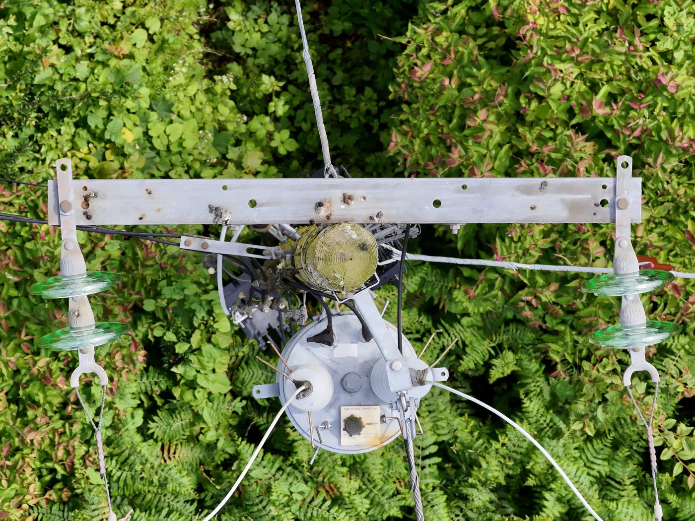
Drone pole inspection — pole-tip & crossarm widths from laser-ranged photos

GeoMeasure turns a single straight-down drone photo into accurate real-world dimensions — pole-tip widths and crossarm spans — scaled from the DJI laser rangefinder. No tape, no climbing, no second site visit.
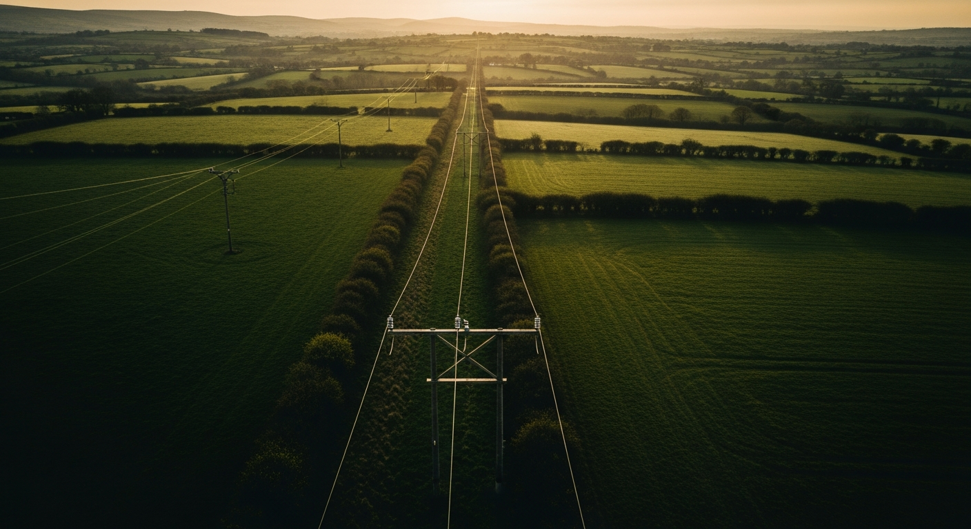
Purpose-built for distribution-pole inspection with a DJI Matrice 4 Series UAS and its laser rangefinder.
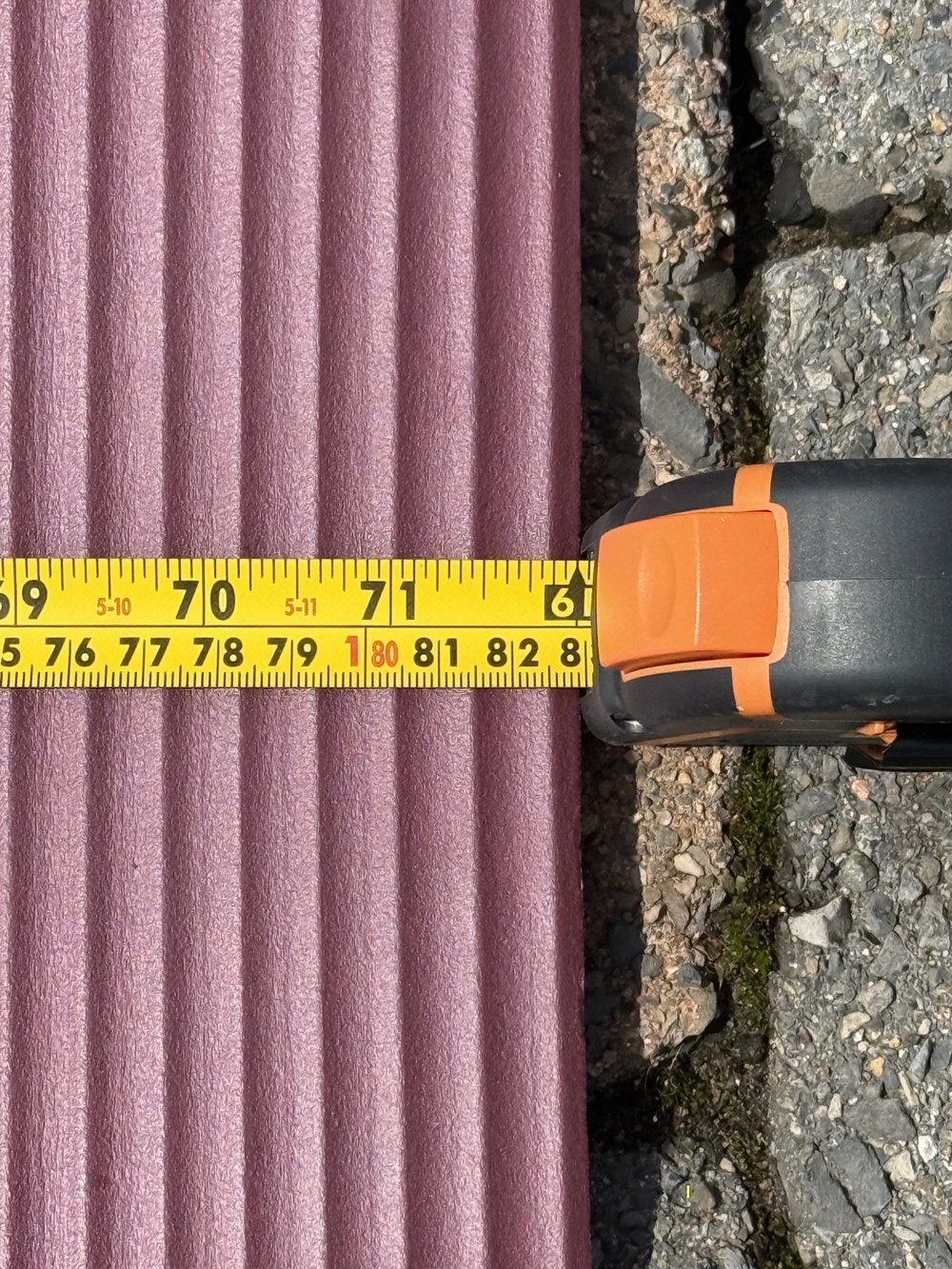
Scale comes straight from the rangefinder distance to the pole tip — corrected per lens and for digital zoom — so sizes read within about ±1% in good conditions.
Fly straight down with the laser on the tip and shoot a single frame. No overlapping flight lines, no photogrammetry, no 3D reconstruction step.
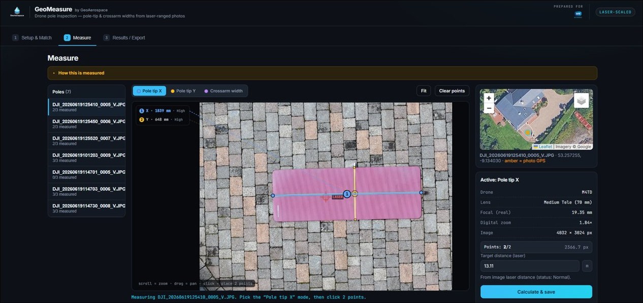
Capture the two pole-tip widths and the external crossarm span on one zoomable canvas, each drawn and colour-coded right on the image.
Add a KML/KMZ of the line and each photo is matched to its pole by GPS automatically — with a manual override whenever you need it.
Each result is flagged Low / Medium / High from off-nadir angle, laser status and range — so you know which numbers to trust at a glance.
Export one tidy row per pole — widths, laser distance, lens, accuracy and confidence — ready for your inspection report or asset system.
Zoom into the nadir image and drop two points. GeoMeasure draws every measurement, colour-coded by axis.
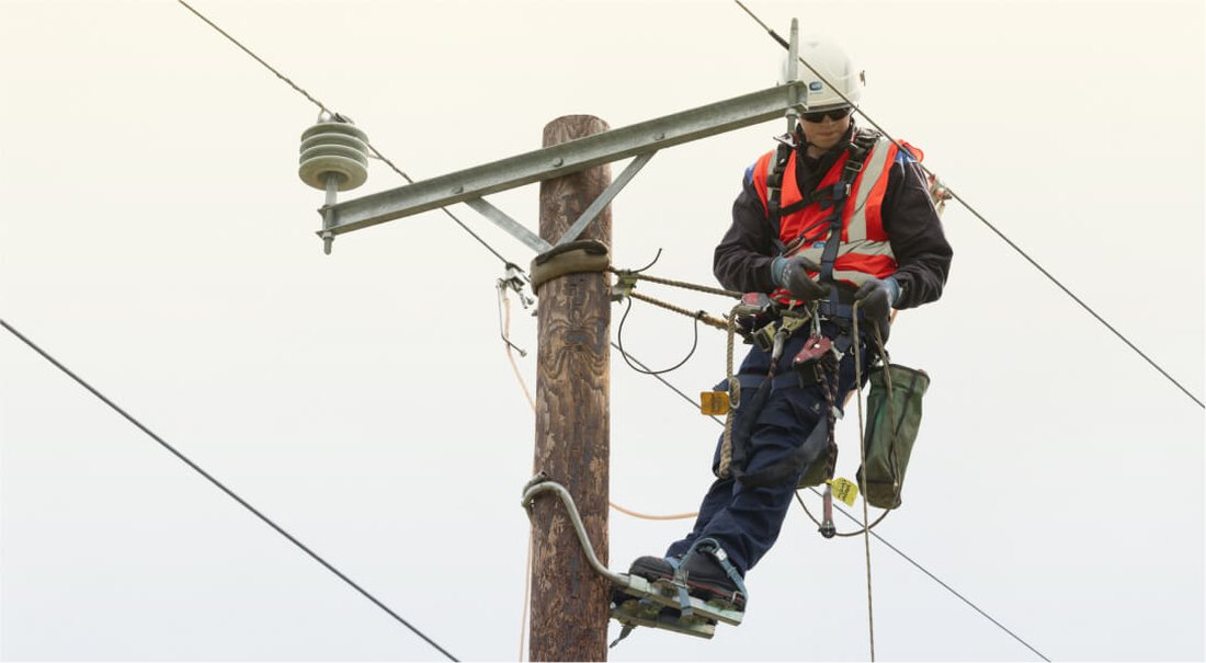
Pole-tip widths and crossarm spans used to mean sending someone up the pole — working at height, beside live conductors, in all weather. GeoMeasure takes those everyday measurements from a single nadir drone photo, so routine sizing no longer carries a climbing or fall risk.
We don’t ask you to take “±1%” on faith. Here’s the calibration test behind it.
Best results come from near-nadir captures (off-nadir close to 0°), a valid laser return, and a moderate standoff. Accuracy degrades on oblique shots or when the laser doesn’t land on the target — which is why every reading carries a Low / Medium / High confidence flag.
Field steps for the drone pilot — one clean, laser-ranged nadir frame per pole.
Take off and bring the drone to the target structure, positioning it directly over the pole so the tip sits in the centre of frame.
Hold a steady hover roughly 11 m above the pole tip (target 10–12 m). This moderate stand-off gave the best ±1% results in testing — flying in close makes the laser scale less reliable.
Set the gimbal to nadir (−90°, 0° off-nadir). The shot must look perfectly straight down — any tilt skews the measurement.
Enable the laser rangefinder and place the laser dot on the pole tip. Wait for a stable reading of about 11 m (10–12 m) — this camera-to-tip distance is what scales every measurement.
Switch to the Zoom lens (3× or 7×) so the crossarm and insulators fill the view — don’t pinch-zoom past the optical tele, which softens detail.
Take a single still JPEG — nadir only, laser active. One photo per pole, then move on to the next structure.
Three stages, from photos to a finished CSV.
Batch-upload your nadir JPGs. Optionally add a KML/KMZ of the line and GeoMeasure matches each photo to its pole by GPS.
Pick a pole, zoom the image and drop two points for each dimension. The laser distance scales it to millimetres with a confidence flag.
Review one row per pole — tip X/Y, crossarm, laser distance, accuracy and confidence — then export the whole survey as CSV.
Upload your first set of nadir photos and export results in minutes.
Batch-upload your nadir JPGs (shot with the laser rangefinder on the pole tip) and head to Measure. Optionally upload the power line as a KML/KMZ (one Point placemark per pole) to label and group images — images are then matched to poles by GPS, override any match below.
Drop JPG images
or browse files
Drop KML / KMZ
or browse
| # | Pole | Assigned image | Match dist. | Laser dist. | Laser status |
|---|
One row per pole: pole-tip width (X & Y) and crossarm external width.
| # | Pole | Image | Tip X (mm) | Tip Y (mm) | Crossarm (mm) | Laser (m) | Acc. | Conf. | Notes |
|---|